

Masonry structures have been and continue to be designed based on the allowable stress design method (also called service load method or working stress design). In this method, a structure is proportioned (designed) to resist code-specified service loads, which are assumed to be loads that a structure might be subjected to during its service life. The allowable (or working) stresses used in design are a fraction of the accepted failure strengths of materials (viz., compressive strength of masonry and yield strength of steel reinforcement) used in design. The structure is so proportioned that actual (i.e., calculated) stresses do not exceed the allowable stresses.
The basic premise of the strength method is that it results in more economical structures and provides more realistic consideration of safety. In the strength design method, the code-specified service loads (such as dead load, live load, wind load, earth pressure, fluid pressure, etc.) assumed to act on a structure are augmented by multiplying with certain factors called load factors (which are different for different loads, also called![]()
![]()


![]()
where, ![]()

![]()

U=the required strength (i.e., effects of factored loads on the structure)
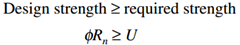
Equation (1) is a generic equation that represents the relationship between the design strength of a structure and the required strength (load effects). On the right-hand side of this equation, U represents the required strength or the effects due to loads, such as bending moment, shear force, axial force, etc., obtained from structural analysis. In specific terms of member strengths, such as moments (M), shear (V), and axial load (P), Eq. (1) can be written as follows:
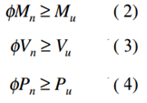
In Eqs. (2) to (4), subscripts n and u denote, respectively, nominal strength and the factored load effects (or demand). The strength reduction factor ![]()
There are many good reasons for applying strength reduction factors to nominal strengths:
1.Actual loads might be different from those assumed in design calculations.
2.Actual load distribution in a structure might be different from that assumed in design.
3.Actual member dimensions might be different than assumed in design calculations.
4.Actual material strengths might be different from those assumed/specified in design.
5.The assumptions and simplifications assumed in design might result in load effects (moment, shear, axial loads, etc.) different from those actually acting on the structure.
6.Actual structural behavior might be different (usually is) owing to the presence of redundancies (influence of rigidity provided by nonstructural members is ignored in structural analysis).
7.Reinforcement might not be in the same exact position as specified by the designer.
To account for these uncertainties, the nominal strength of a member is reduced by multiplying it with the strength reduction factor ![]()